
Senior Capstone Project: Morphing Sail
- Gilbert Tohme
- Nov 24, 2023
- 7 min read

Updated: Jun 26, 2024
This project centered on developing an automated morphing wingsail system aimed at improving the efficiency and sustainability of maritime transportation. The primary objective was to reduce fuel consumption and carbon emissions within the shipping industry.
I collaborated within a team of 6 Mechanical Engineering students, and I focused specifically on the design aspects of the wingsail. My responsibilities encompassed the structural, mechanical, and aerodynamic elements of the wingsail's development.
Design and Development
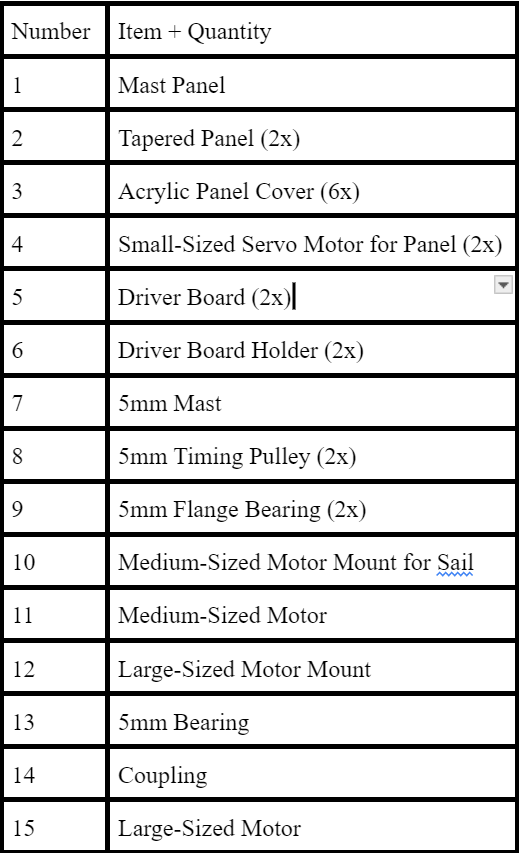
We began by conceptualizing a 9-panel wingsail system, aiming for optimal aerodynamic performance and structural integrity. Using SolidWorks's Flow Simulations feature, we tested various configurations to optimize lift and drag characteristics. The design underwent many iterations and testing, where we ultimately switched to a streamlined 3-panel design to address weight issues, specifically with the side panels, which was hindering the morphing motors' ability to rotate and fold the sail. Here is the SolidWorks Model and physical prototype of our final design, with the corresponding legend below:

Manufacturing Process
Below is a structured breakdown of the design steps for this project, categorized by process:
3D Printing:
Panels: We used a Bambu X1 FDM printer to fabricate the panels. This particular printer guaranteed precise quality prints, essential for the structural integrity, aerodynamics, and aesthetics of the parts.
Mounts: We used the same printer to print out the small, medium, and large motor mounts as well as the driver board mount.
Lathe turning:
Mast rod: A 5mm shaft connects the mast to the medium motor fixture. We used a lathe to slightly reduce the diameter of the shaft's bottom part, which gave it an adequate tolerance that let us easily insert it into the flange bearings.
Laser cutting:
Acrylic Sheets: Following the 3D printing phase, we laser cut 12" x 16" acrylic sheets, each with a 1/16" thickness using an 80W Epilog Fusion Edge CO2 laser cutter. This process ensured accurate sizing of the panels. After cutting, we cleaned the edges using isopropyl alcohol to remove residue without damaging the material.
Secondary Processes / Adhesives:
Acrylic Panel Attachment: We used JB Weld Plasticbonder epoxy to attach the acrylic panels to the 3D-printed structure. This adhesive was ideal for providing a strong plastic-to-plastic connection.
Assembly Operations / Fasteners:
Assembly of Panels and Motors:
The panels were attached using a notch extrusion on the top and secured at the bottom by sliding the shafts of the small motors into the adjacent panels.
The motors were fastened securely with screws onto the motor mounts at the bottom of each panel.
Each motor was paired with driver board and then attached to the sail.
Attachment of Motors:
Both the large and medium motors were securely affixed to their respective mounts using screws to ensure stability.
Mast Shaft Preparation:
The 5mm shaft was fixed in position with a screw on the mast.
Belt Installation:
As shown below, a short belt was cut and installed between the medium motor shaft and the shaft in the mast. This belt facilitated the rotational movement of the sail, completing the assembly process.

Mast Shaft Installed with Screw
Simulation and Testing
SolidWorks Simulations: Enhancing Design and Performance:
I used SolidWorks to conduct Computational Fluid Dynamics (CFD) simulations, analyzing lift and drag at different camber orientations and angles of attack so that we could understand airflow patterns and optimize our wingsail design for efficiency and stability. To ensure accuracy, I scaled the wind speeds using the Reynold’s Number equation, simulating conditions at both 550 m/s and 2.5 m/s.
Simulation Test Results at Different Angles of Attack:
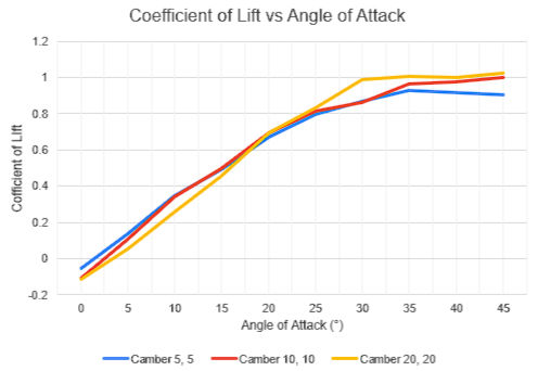
Before switching to a 3-panel wingsail, I tested the original 9-panel design under various wind speeds and angles of attack. After redesigning to 3 panels, the simulations indicated good performance at 550 m/s across different angles of attack. The 3 configurations in this graph are symmetric, with end panels at 5°, 10°, and 15° from the mast. The results show similar performance for each configuration. Unlike typical aircraft wings, which peak at about 15° angle of attack, our simulations show peaks at about a 45° angle of attack.
Functionality Testing:

Experimental Setup
As a team, we tested the physical prototype under different wind conditions using a testing rig with wheels, shown above in Experimental Setup. Despite the challenge of achieving 550 m/s wind speed, the prototype showed promising results with a box fan blowing out wind at a speed of 2.5 m/s. The system demonstrated efficient stowage, minimal deck interference, and significant lift.
Calibration for Physical Test:

We used a force sensor (FSR), shown above in Experimental Setup, to precisely measure the lift and drag forces exerted on our wingsail prototype during physical testing. To ensure its accuracy, we calibrated it by analyzing mass-force-voltage relationships under various wind conditions. With the fan speed set to 2.5 m/s, we tested different masses on the sensor, creating a linear force-voltage relationship and validating our force measurements.
Physical Test Setup:
We conducted physical tests using the fan, which was placed 2 ft from the sail system, adjusting the orientation and fan speed to simulate different wind conditions. These tests helped us understand the aerodynamic performance of the prototype.
Physical Test Results:


Bending and Shear Stresses on Mast
The analysis of bending and shear stress on the mast tell us about its structural integrity and durability. These calculations reveal the maximum forces experienced by the mast, aiding in understanding its capacity to withstand loading without failure. With a safety factor of 25.78 for bending stress and 47,391.14 for shear stress for the prototype, the mast demonstrates ample strength and resistance, ensuring structural stability and reliability during operation.
Comparison between Simulations and Physical Testing:
While the simulations provided valuable insights, physical testing with a fan at 2.5 m/s validated our findings. The experimental data below shows slight deviations from theoretical predictions, especially at higher angles of attack, but overall, the wingsail design performed well under various conditions:


For these pieces of data, the orientations we had the lateral and tail wind scenarios are:
Angle Orientation for Lateral Wind Scenario

Angle Orientation for Tail Wind Scenario

In the tailwind scenario for Camber 10, 10, the experimental data initially shows lower thrust force compared to theoretical predictions but surpasses them slightly at a 45° angle of attack. This trend is also seen in Camber 20, 20, indicating slight deviations between the experimental and theoretical outcomes as the angle of attack increases.
In the lateral wind scenario for both Camber 10, 10 and Camber 20, 20, the theoretical thrust force consistently exceeds the experimental measurements at all angles of attack. This showcases the limitations we had in accurately estimating thrust using only theoretical calculations, particularly at higher angles of attack where more turbulent aerodynamic behavior and flow separation became apparent.
Despite these limitations, our wingsail design demonstrated strong performance across various conditions. Performing relatively accurate simulations and physical testing ensured our design's efficiency and stability.
Market Value and Impact
The maritime industry is increasingly focused on sustainability due to regulatory mandates and environmental concerns. According to market research firm Grand View Research, the marine propulsion engine market, valued at USD 11.64 billion in 2020, is projected to reach USD 15.92 billion by 2028, growing at a 3.9% CAGR. Stricter IMO regulations and the demand for eco-friendly technologies are pushing shipowners towards alternatives like our morphing wingsail system. A scaled-up version of our design can save up to 21% on fuel costs, offering significant environmental benefits and cost reductions, and can be used on ships such as the Supramax Dry Bulk Carrier.
For instance, on a shipping route between Shanghai and Los Angeles, our system can reduce fuel consumption from 2567.25 tons to 2028.1 tons, cutting costs by $296,178 per trip. The investment of $1,250,000 for 5 wingsails pays back in just 2.81 months, making it a financially attractive option for shipping companies should it be manufactured in real life.
Conclusion and Recommendations
Moving forward, we identified several areas for improvement and further exploration:
Fragile and Brittle Parts:

Crack location on old panel laser cut
Some 3D-printed parts snapped during handling and assembly. We had to glue broken pieces together, which compromised the wingsail's integrity. Future assembly should involve inserting the acrylic on a flat surface rather than free-holding it.
Stub Shearing Issue:

Metal rod stub
The stub on top of a panel sheared off easily. We temporarily fixed this by drilling a hole, inserting a metal rod, and gluing it. Future designs should increase the shear strength of the 3D-printed stub or use metal rod stubs for all panels.
Glue Residue Problem:

White stains from conventional glue
Conventional glue left residue and stains on the panels. Using black glue specifically for plastic applications resolved this issue.
Print Quality Inconsistency:
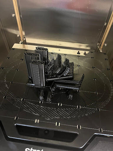
Failed 3D Print from the Stratasys printer
The attachments housing the motors were 3D printed independently from EPIC’s Stratasys F370CR printer. However, due to issues such as having to split our parts to fit within its print dimensions and experiencing poor print quality as shown above, we switched to the Bambu Lab X1 printer for the final prototype, which allowed for high print speeds while maintaining print quality, introducing a significant improvement in our manufacturing strategy.
Wind Tunnel Testing:
We wish we had conducted actual wind tunnel testing to compare simulation data with real-world results. However, BU's Wind Tunnel was not in proper working condition during our project, which would have introduced many inaccuracies in our measurements. Had the wind tunnel been available AND more accurate, it could have provided more accurate results than using the fan.
Camber Adjustments:
We sough the need to refine camber adjustments several times through additional simulations. This helped us determine the optimal configuration for different angles of attack and wind speeds, potentially maximizing performance.
Model Boat Testing:
Testing the system on an actual model boat rather than a simple car-shaped rig would have been beneficial to assess its real-life functionality. This would offer a practical demonstration of the system's stability, maneuverability, and overall effectiveness in a dynamic setting, and even allowed us to physically test our model on water.
Finally, here is a SolidWorks model of what our sail would look like scaled up for real life ships like the Supramax Bulk Carrier!

And here is a picture of the complete project, with the electronic automation and Arduino equipment connected to our wingsail:


Comments