
EK301 Project: Truss Build
- Gilbert Tohme
- May 16, 2022
- 3 min read

Updated: Jun 26, 2024
This project spanned from March 2022-April 2022 and it was completed during the Spring 2022 semester of my sophomore year. It in, my group and I and constructed a truss made out of acrylic bars. In the building of this truss, we had to satisfy a series of physical and financial constraints that could pass the buckling test and correctly predict which members would buckle first.
Our main priority of the bridge design was to strive for the highest maximum buckling load, as ultimately, bridges are supposed to be able to withstand large weight load. Additionally, because we knew having a sturdier structure is more valuable than a cheaper design, we added as much support across all joints and members as possible. We wish to determine the critical pressure, which represents the critical buckling load for each acrylic strip loaded in pure axial compression, and simply supported at its ends. For this reason, when we were predicted which members would buckle first, we only considered members that we calculated under compression.
In our final design, we constructed a truss that resembles the Camel Back Truss configuration. A sketch of the final design can be seen below:

Figure 1: Final Truss Design, as made on the Johns Hopkins University Truss Simulator. This includes a diagram of our truss, as well as each member and joint (node) and corresponding lengths in inches as well as the pin, horizontal roller, and external force that would act on the truss upon testing.
With this design, we were able to satisfy all the physical constraints, including but not limited to:
The truss must be a single, planar truss where the members cannot be designed to extend below the line connecting the two end joints.
The number of members and the number of joints must be related by M = 2J - 3, where M represents the number of members and J represents the number of joints.
The truss must support a minimum live load of 32 oz. and it must be placed on a joint located at a horizontal distance of 20 in. away from the pin support.
The joint-to-joint span for each individual member must be between 8.5 in. and 15 in.
We also satisfied all the financial constraints, including:
The total virtual cost of the truss must be less than $295, where the cost of the truss is defined as Cost = C_1 * J + C_2, where C_1 = $10/joint and C_2 = $1/in.
The cost here is defined as virtual because we only applied this constraint into our completed MATLAB calculations, alongside the internal forces on each member and the predicted critical buckling loads.
Our primary issues we came across while designing this truss were that we initially failed to support a minimum load of 32 oz. Specifically, our truss could only hold up to 28 oz. and to resolve this, we added more joints and triangular support systems to our truss. Specifically, we added 8 joints and 13 members to our final design, coming out to a final virtual budget of $224.70 and a small load/cost ratio of $0.19 oz/$.
Upon solving this and retesting our final design with our MATLAB code, we came up with a final prediction about which member would buckle first. It was important to keep in mind that only members that buckled in compression could buckle first because their bending moments, or reactions to an applied force on an object, would be higher than for members that buckled in tension. In other words, we were looking for the member that would buckle first as the buckling load is applied, and this would give us the lowest possible buckling load value.
Thus, we predicted that member M4, with the lowest magnitude of the max buckling load (15.33 oz) would buckle first. Our prediction ended up being correct upon testing with several sample weights. In fact, our truss model was able to hold a lot more weight than we originally anticipated, at nearly 3 kg!
Below are some picture our final truss build. The top picture depicts the bridge as is, while the bottom picture showcases its buckling effects once we placed a set of weights at the 20 in. location.
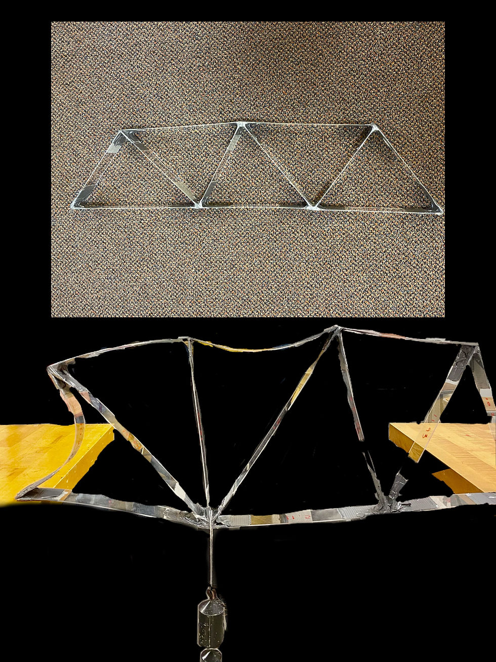
Figure 2: Physical Build of Final Truss Design, shown buckling across most of its joints due to the weights attached to the bottom, and the non-buckling free-standing build as shown towards the top


Comments